Chasing an audio artifact on power loss
First off, I have a fully assembled production candidate prototype in a production candidate case! More on that to come, stay tuned!
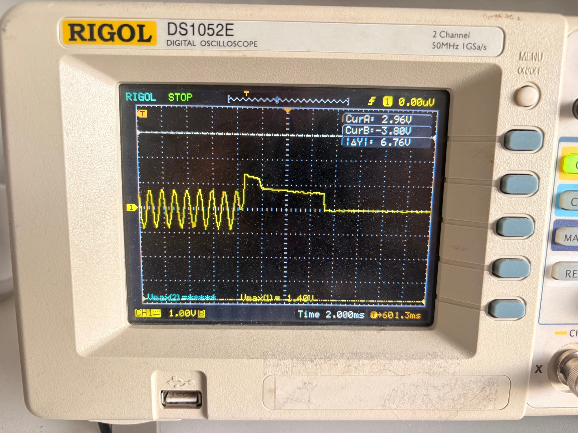
For about a year I had been trying to figure out how to solve a problem with the audio stage of the SA-01: when the synth lost power, whether switching the power switch off or yanking the USB cable, I could hear a "click" or "thunk" out of the PCM5102A DAC's line out (and, naturally, amplified through the headphone amplifier). I measured it, and while it was unlikely to damage headphones, it bothered me and I wanted to fix it.
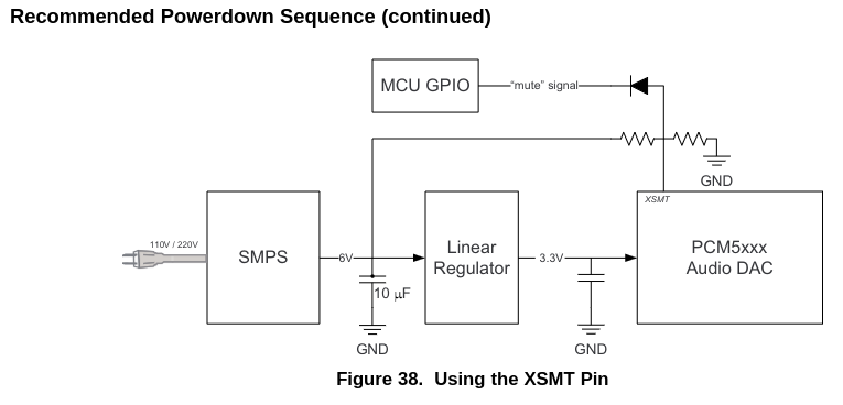
I read the DAC's datasheet about unexpected power loss several times. The chip has a pin that can be used to mute outputs with a specific circuit specified for handling unplanned power loss. I wired up this exact circuit - a voltage divider drawing power from the upstream 5V power source to signal to the chip that it's about to lose power - and still, the click persisted!
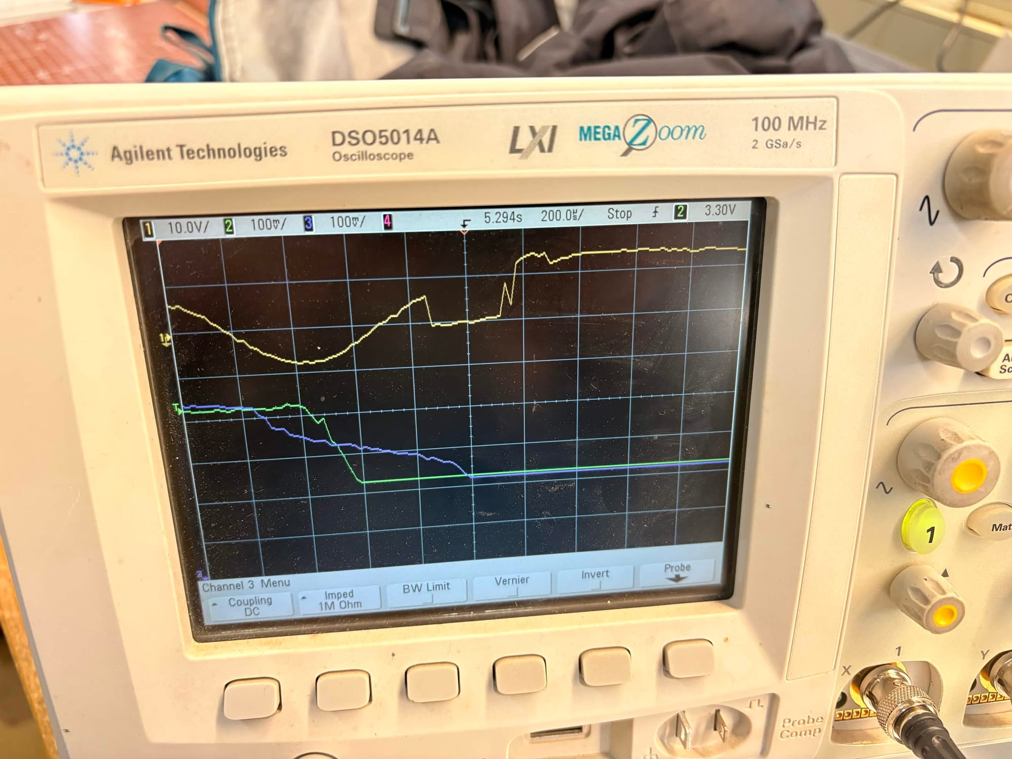
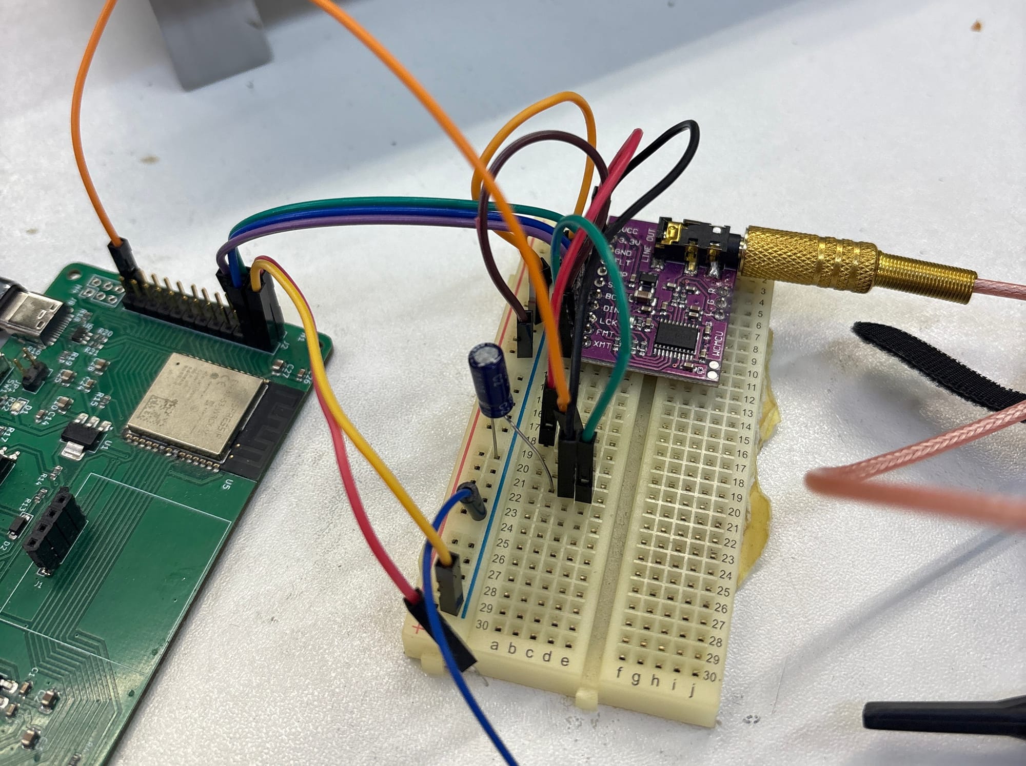
At this point I put oscilloscope probes on the 5V rail, 3.3VA rail and DAC output. After much staring at readings I, with the help of a few friends at the Vancouver Hack Space, realized that the voltage spike is happening after the chip has already stopped! This wasn't a problem with muting at all. Taking a guess that maybe my understanding of the timings was wrong and the chip needed more time to gracefully switch off its outputs, we put a bunch of extra bulk capacitance on the breadboard (a 220uF electrolytic cap). Like magic, the voltage spike was gone! I wasn't sure I fully understood the problem, but I had a solution - in testing, even 100uF was enough to keep the chip alive long enough to power off quietly (in this circuit). I wasn't completely clear on why this worked, but at this point I was ready to move on.
When I reworked my circuit for the next iteration of the SA-01 mainboard I implemented this fix - an extra 100uF of bulk capacitance hanging off the 3.3VA rail. My mechanical design is vertical space constrained, so I've been exclusively using surface mount ceramic MLCC capacitors. I had heard that electrolytic caps were best for bulk capacitance, but ceramics had worked fine everywhere else - what could be the issue?
Fast forward many months after I actually got around to finishing the next revision of the boards, got them back - everything worked except the voltage spike! It was still there! What!
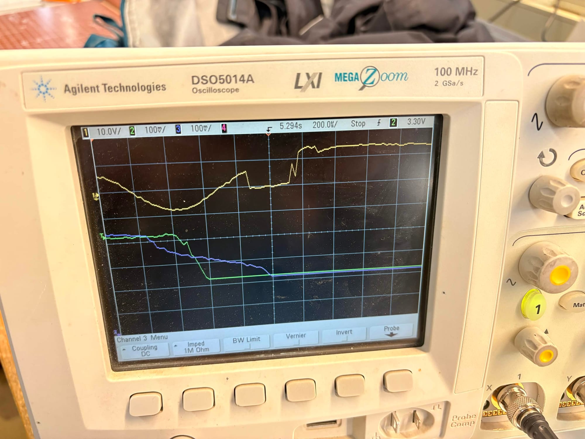
I wired up the same circuit on a DAC to run another experiment. Same problem, same solution. On a whim I started looking at the differences in capacitors behaviours, since that's the only difference between the breadboarded solution and my faulty board. Sure enough, MLCC capacitors, especially small ones like my 0805s, lose up to 50-60% of their capacitance under bias! I only really added 50uF to my 3.3VA line, far less than the 100uF I had tested with! To confirm this, I performed a hacky bodge fix and attached a 220uF electrolytic capacitor to the SA-01's 3.3VA line and huzzah, no voltage spike! For the next board, I will make room for a 220uF electrolytic capacitor. I could probably get away with a bunch of extra MLCC caps, but at this point I'd rather just stick with what I know works.
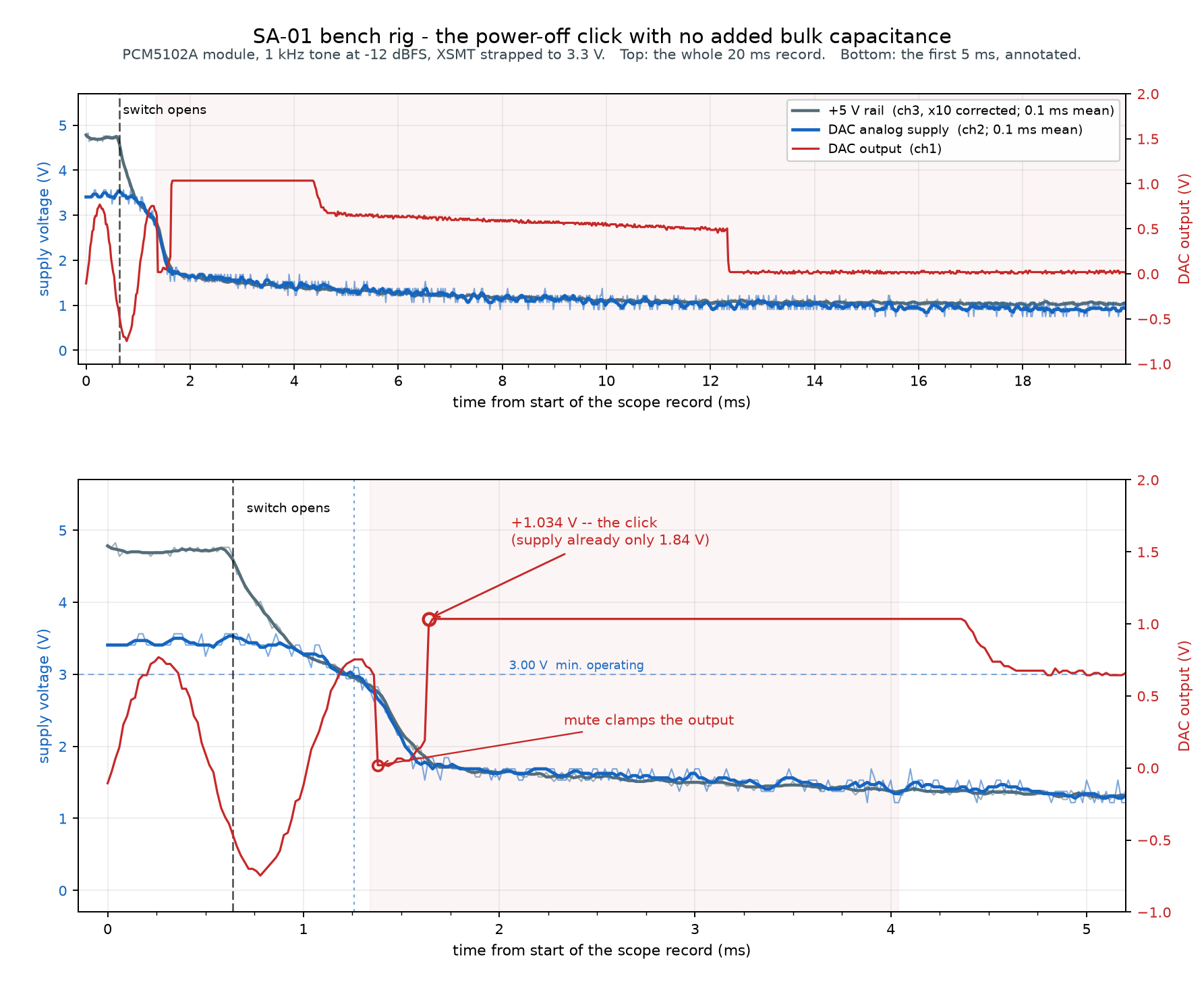
So what actually is that voltage spike on power loss? It's clear that the chip self mutes just fine - in some captures I can actually see the quantization of the output being stepped down to 0V - the artifact happens after muting has completed. My understanding: when main power is cut, the ESP32 loses power immediately, resulting in the I2S clock going silent. The DAC detects this and mutes itself, but it still needs enough time to hold the output to 0V while the residual energy in the capacitors dissipates. If it doesn't have sufficient time, the energy in the charge pump capacitors is dumped on the line out, resulting in our artifact. The TI datasheet actually does sort of explain this:
Under certain conditions, the PCM510xA devices can exhibit some pop on power down. Pops are caused by a device not having enough time to detect power loss and start the muting process.
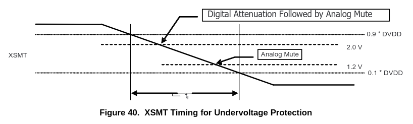
What I didn't realize is that the power has to be held for long enough after the mute completes - the datasheet isn't entirely clear on this. The unplanned voltage loss feature in the DAC expects the power to fail over 6 or more milliseconds, far longer that our ~1 millisecond power loss. This protection never kicked in - the chip had already muted itself due to lack of I2S data - but that slow fall is still necessary for a graceful power loss.
Mystery solved! Silent power loss!
Demo of the nearly fully assembled first prototype